 This card guide is in accordance to specification IEEE 1101.10. The required coding of the IEEE is integrated in the card guide head. With provision for the IEEE contact spring for groun ding of the alignmentpins of the PCB‘s front panel. Also with a provision for contacting a track near the PCB edge. This snap-in card guides can be secured with screws.
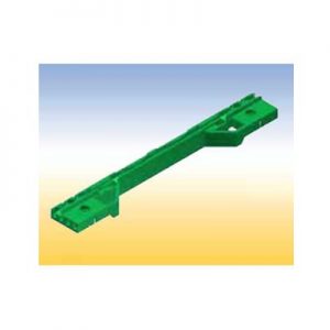
 This card guide is also in accordance to specification IEEE 1101.10. For CompactPCI-power supplies and for Plug-in units fitted with SMD. With provision for the IEEE contact spring for grounding of the alignment pins of the PCB‘s front panel. Also with a provision for contacting a track near the PCB edge. This card guide is secured with screws.
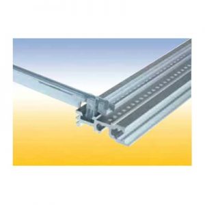 This is an all purpose card guide with provision for a spring to contact front panels.
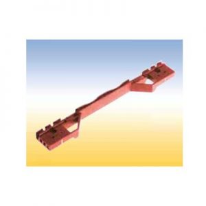
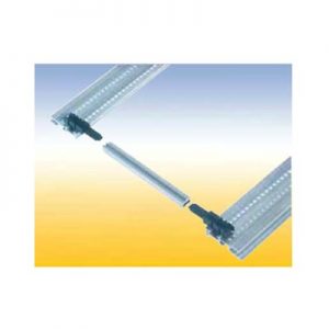 This is a length variable card guide constructed from 3 pieces. The center piece can be cut to any length. With a provision for a spring to contact front panels. These snap-in end pieces can also be secured with screws.
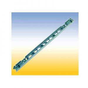 Lattice construction for heavy mechanical loads. With a provision for a spring to contact front panels and for contacting a track near the PCB edge. This card guides can be snapped in and/or secured with screws. Two versions: 1. With pressed-in nut M 2.5 for assembly to the horizontal rail with oval head screws M 2.5 x 12 2. Without a nut, but one can be added in the existing hexagonal molding.
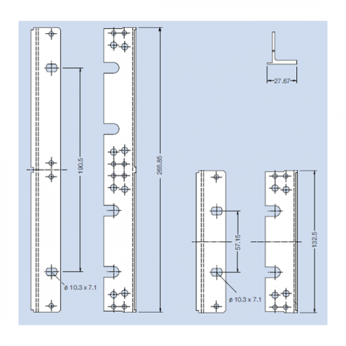
 The flange can be mounted to the side panel by means of the mounting screws for the horizontal rails. Material: aluminum, extruded Finish: anodized
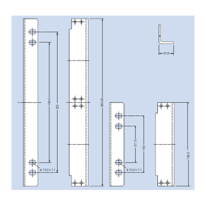 Flange for Wall Mounting For mounting of a subrack on a wall. Material: aluminum Finish: blank, seawater resistant
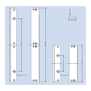 This flange is suitable for mounting of a continous front panel of 85 HP and a hinged front panel of 85 HP in a subrack. The flange will be mounted to the side panel by means of the mounting screws for the horizontal rails. Material: aluminum, extruded Finish: colorless chromated
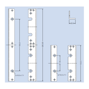 Flange without Nose This flange can be mounted at various depth on the side panel grid. Material: aluminum, extruded Finish: anodized
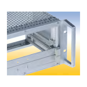 Material: aluminum Finish: anodized
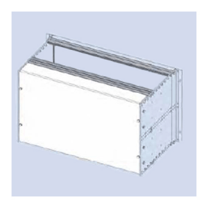 Rear Cover F 84 HP For covering the wiring field of the subrack
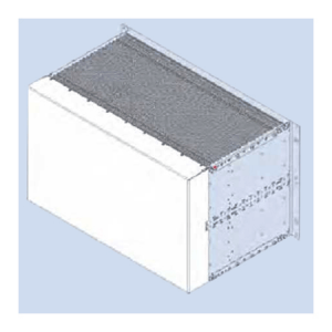 Rear Cover RFI 84 HP Protective wiring rear cover for RFI shielded enclosure. Material: aluminum, 1 mm thick Finish: colorless chromated
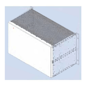 Rear Cover RFI 84 HP, inside Protective wiring rear cover for RFI shielded enclosure. Material: aluminum, 1 mm thick Finish: colorless chromated
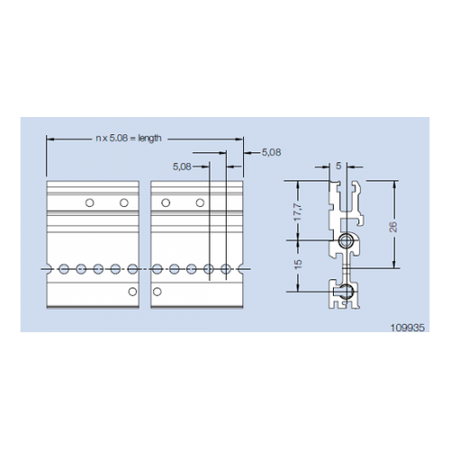 Rear Profile H22-RFI for screw on rear cover (type delta) For use with a rear cover. Material: aluminum Finish: colorless chromated
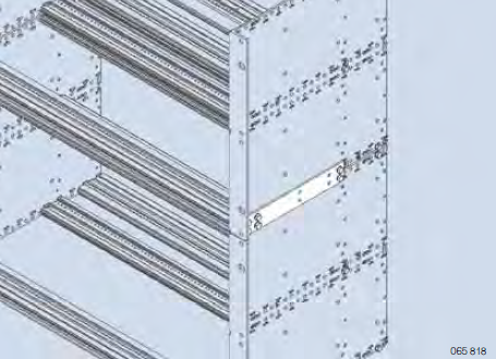
 Side Panel Connector Join two subracks, one above the other. The side panel connector is mounted to the side panels by means of the mounting screws for the horizontal rails. (nom. depth 160 mm). Material: aluminum, 2 mm thick Finish: blank
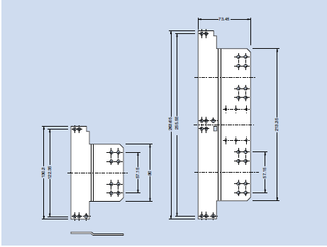
 Side Panel Extender Elongate a side panel about 60 mm to obtain a larger cabling space. The side panel extender is mounted to the side panel by means of the mounting screws for the horizontal rails. Material: aluminum, 2 mm thick Finish: colorless chromated
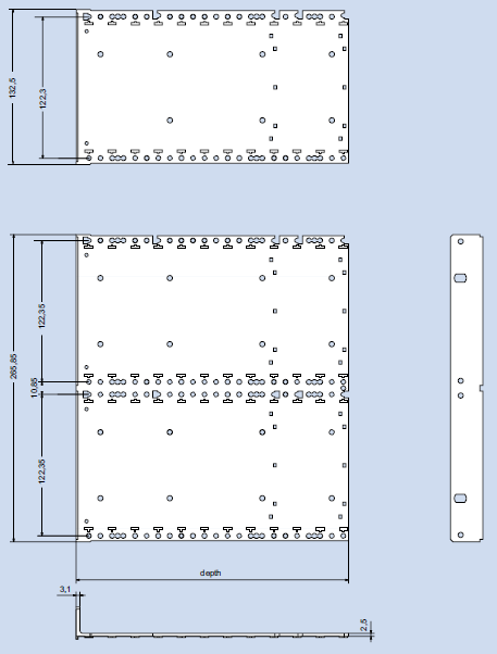
 Side Panel Fi (flange integrated) The side panel and the flange are extruded in one piece. Material: aluminum, extruded Finish: colorless anodized or colorless chromated
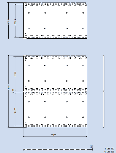
 Material: aluminum, extruded Finish: colorless chromated
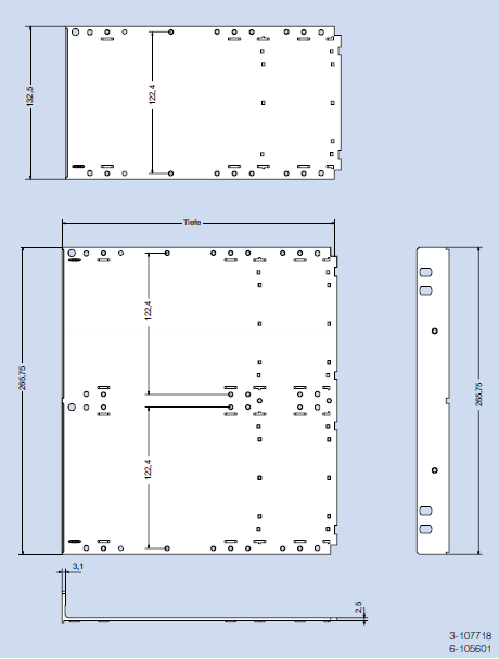
 Material: aluminum, extruded Finish: colorless chromated
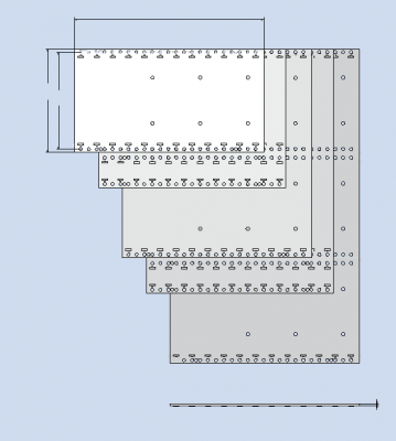
 Side Panel RFI without flange Material: aluminum, 2.5 mm thick Finish: blank, seawater resistant
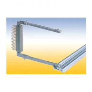 For easy screwless snap-on mounting of connectors accordance to IEC 60 603/ DIN 41 612. With a provision for a spring to contact front panels and for contacting a track near the PCB edge. This snap-in card guides can als be secured with screws.
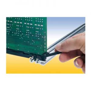
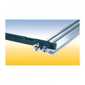 Card Guide with integrated push and pull assist This special card guide with an integral small lever aids in the handling of PCB’s with high pin plug in connectors. The lever is supported by the walls of a special guide chamber when the board is pulled out or pushed in. It is suitable for a spring to contact a track near the PCB edge. This card guides are snapin and can be secured with screws.
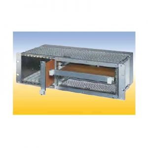 20 HP for horizontal mounting of 6 U PCB‘s in 3 U subracks. The horizontal mounting frame needs 52 HP in the width. For 84 HP subracks are available Placed right: 52 HP for horizontal mounting frame, 32 HP for 3 U PCB‘s Placed left: 52 HP for horizontal mounting frame, 1 HP for air and leakage paths, 31 HP for 3 U PCB‘s.
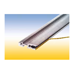 Self adhesive. For identifiying PCB slots in the subrack. The PCB slot number can be read thru the hole in the front panel. Note: The label strip cannot be read while using the RFI spring P2. Material: PC/PE foil Color: yellow/black