 This card guide is in accordance to specification IEEE 1101.10. The required coding of the IEEE is integrated in the card guide head. With provision for the IEEE contact spring for groun ding of the alignmentpins of the PCB‘s front panel. Also with a provision for contacting a track near the PCB edge. This snap-in card guides can be secured with screws.
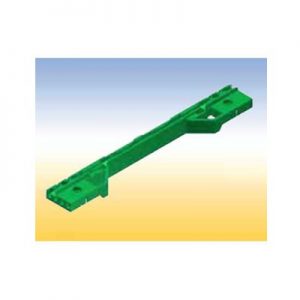
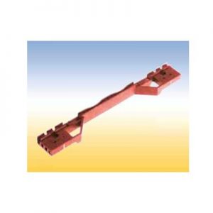
 This card guide is also in accordance to specification IEEE 1101.10. For CompactPCI-power supplies and for Plug-in units fitted with SMD. With provision for the IEEE contact spring for grounding of the alignment pins of the PCB‘s front panel. Also with a provision for contacting a track near the PCB edge. This card guide is secured with screws.
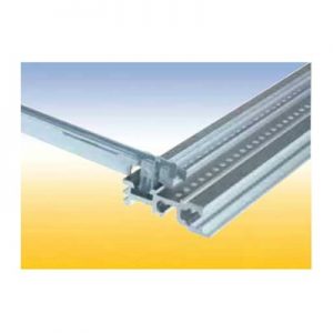 This is an all purpose card guide with provision for a spring to contact front panels.
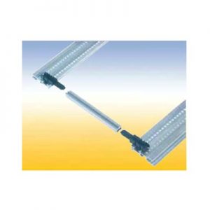 This is a length variable card guide constructed from 3 pieces. The center piece can be cut to any length. With a provision for a spring to contact front panels. These snap-in end pieces can also be secured with screws.
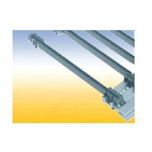
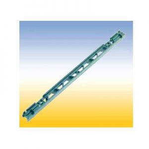 Lattice construction for heavy mechanical loads. With a provision for a spring to contact front panels and for contacting a track near the PCB edge. This card guides can be snapped in and/or secured with screws. Two versions: 1. With pressed-in nut M 2.5 for assembly to the horizontal rail with oval head screws M 2.5 x 12 2. Without a nut, but one can be added in the existing hexagonal molding.
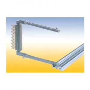 For easy screwless snap-on mounting of connectors accordance to IEC 60 603/ DIN 41 612. With a provision for a spring to contact front panels and for contacting a track near the PCB edge. This snap-in card guides can als be secured with screws.
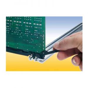
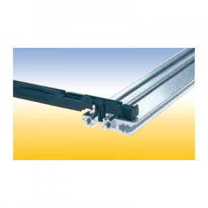 Card Guide with integrated push and pull assist This special card guide with an integral small lever aids in the handling of PCB’s with high pin plug in connectors. The lever is supported by the walls of a special guide chamber when the board is pulled out or pushed in. It is suitable for a spring to contact a track near the PCB edge. This card guides are snapin and can be secured with screws.
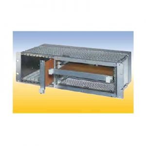 20 HP for horizontal mounting of 6 U PCB‘s in 3 U subracks. The horizontal mounting frame needs 52 HP in the width. For 84 HP subracks are available Placed right: 52 HP for horizontal mounting frame, 32 HP for 3 U PCB‘s Placed left: 52 HP for horizontal mounting frame, 1 HP for air and leakage paths, 31 HP for 3 U PCB‘s.
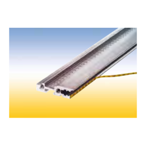 Self adhesive. For identifiying PCB slots in the subrack. The PCB slot number can be read thru the hole in the front panel. Note: The label strip cannot be read while using the RFI spring P2. Material: PC/PE foil Color: yellow/black
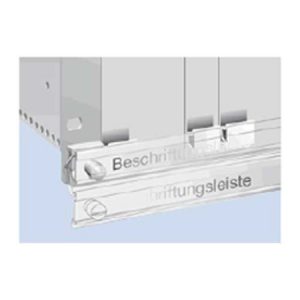 This hinged labelling rail is mounted on the subrack flanges. Normally it is placed in front of the front panels. For ejecting a PCB, the rail is turned down.
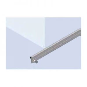 For locking of PCB‘s witout front panels. The locking rail is mounted at the horizontal rail in front of the PCB‘s. A labeling strip can be insert into a groove.
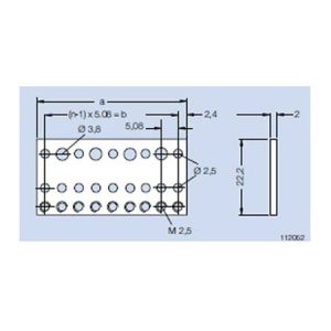 Mounting Rail B tapped M 2.5 For mounting connectors in accordance to IEC 60 603/ DIN 41 612. For mounting at the rear profile on subracks type alpha with insulating strip and insulating bushings. For mounting at the rear profile on subracks type delta. Material: aluminum Finish: blank
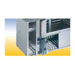 Partition Wall For partitioning of a subrack part. The partition wall 6 U can also be used as a RFI shielded subrack divider in 6 U and 2x3 U parts.
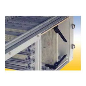 Secures PCB’s without front panels. Used for easy locking and ejecting of PCB’s
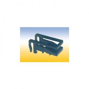 Secures PCB without front panels.
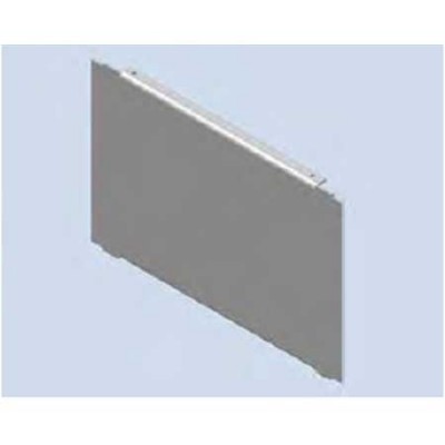
 Separating Wall For separating a subrack int two fields. Material: aluminum Finish: blank Delivery: 1 separating wall Mounting parts
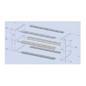 Subrack Divider Kit 2 x 3 U - 42 HP and 6 U - 40 HP The divider separates a 6 U subrack into a field for 6 U PCB’s and 2 fields of 3 U. Finish: colorless chromated Delivery: 1 double front profile 2xVE1 43 HP chromated 1 double rear profile 2xHK 43 HP anodized 2 divider strips Assembly: Mounting parts
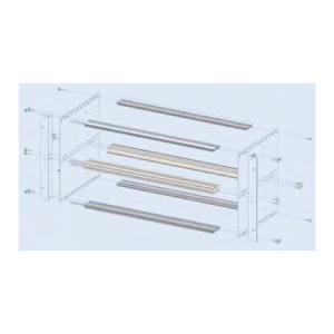 Subrack Divider Kit 2 x 3 U - 84 HP For partitioning a 6 U subrack in 2 x 3 U.
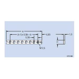 Threaded Strip M 2.5 For attaching the front panels and assembly parts at the wiring field. Material: steel Finish: galvanized, chromated
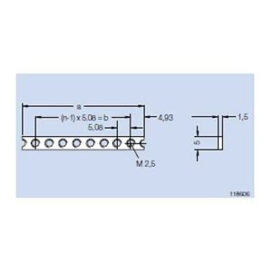 Threaded Strip M 2.5 - stainless steel For attaching the front panels and assembly parts at the wiring field. This threaded strip is for nonmagnetic applications. Material: stainless steel Finish: blank
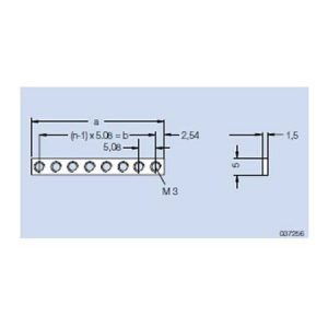 Threaded Strip M 2.5 addable This threaded strip could be added to other strips and the space between the holes always adds up 5.08 mm. Material: steel Finish: galvanized, chromated
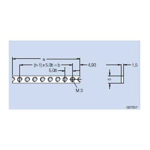 Threaded Strip M 3 Material: steel Finish: galvanized, chromated
 Threaded Strip M 3 addable Material: steel Finish: galvanized, chromated
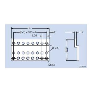 Z-Rail A tapped M 2.5 For mounting connectors in accordance to IEC 60 603/ DIN 41 612 in subracks type alpha. Mounted on the rear profile. Material: aluminum Finish: colorless chromated
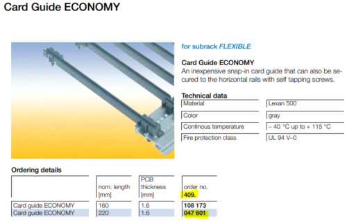
 For subrack FLEXIBLE Card Guide ECONOMY An inexpensive snap-in card guide that can also be secured to the horizontal rails with self tapping screws. Technical data Material Lexan 500 Color gray Continuous temperature – 40 °C up to + 115 °C Fire protection class UL 94 V–0
- For subrack FLEXIBLE Card Guide ECONOMY An inexpensive snap-in card guide that can also be secured to the horizontal rails with self tapping screws. Technical data Material Lexan 500 Color gray Continuous temperature – 40 °C up to + 115 °C Fire protection class UL 94 V–0 For card guide 1.6-220, see part number 409-047-601