 This is an all purpose card guide with provision for a spring to contact front panels.
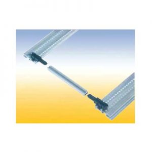
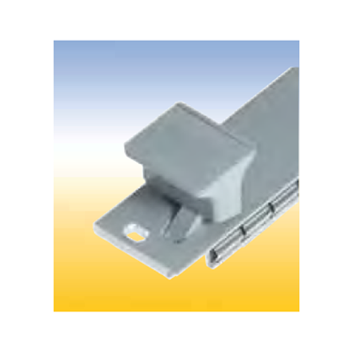
 This is a length variable card guide constructed from 3 pieces. The center piece can be cut to any length. With a provision for a spring to contact front panels. These snap-in end pieces can also be secured with screws.
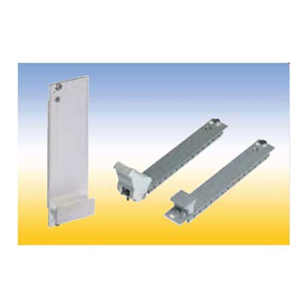
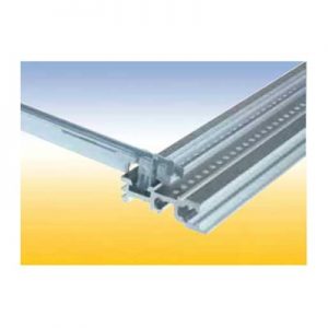
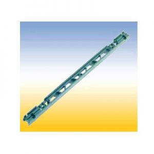 Lattice construction for heavy mechanical loads. With a provision for a spring to contact front panels and for contacting a track near the PCB edge. This card guides can be snapped in and/or secured with screws. Two versions: 1. With pressed-in nut M 2.5 for assembly to the horizontal rail with oval head screws M 2.5 x 12 2. Without a nut, but one can be added in the existing hexagonal molding.
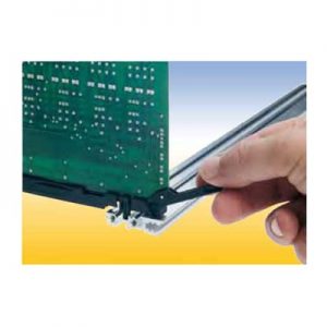
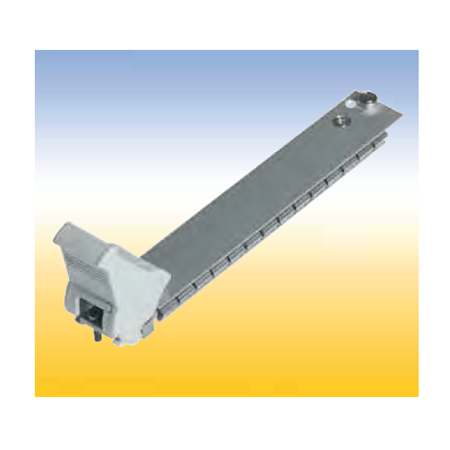
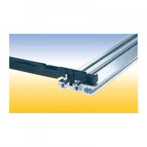 Card Guide with integrated push and pull assist This special card guide with an integral small lever aids in the handling of PCB’s with high pin plug in connectors. The lever is supported by the walls of a special guide chamber when the board is pulled out or pushed in. It is suitable for a spring to contact a track near the PCB edge. This card guides are snapin and can be secured with screws.
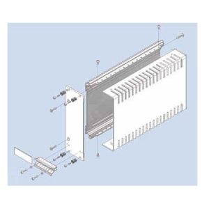 Cassette with Cover Hood Kit constists of: 1 extruded side wall 1 cover hood 1 front panel, with slits in the side edges for insertion of RFI gaskets 1 handle 1 aluminum ident plate Mounting parts
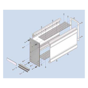
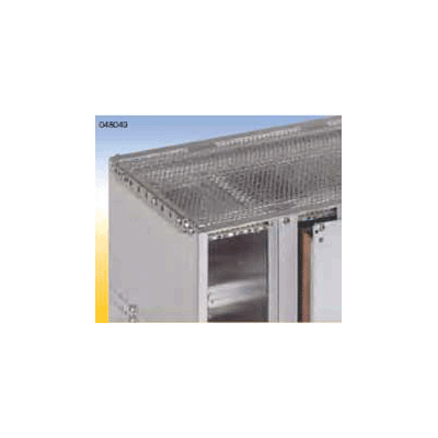
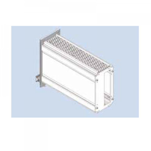 Cassette with Extruded Side Walls The cassette kits includes following rear panels: 1. Rear panel closed (RG) 2. Rear panel with partical aperture (RT) 3. Rear panel with full aperture (RV).
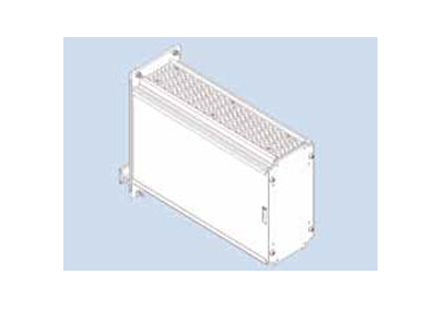
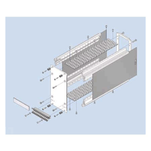
 Cassette with four Depth Profiles The cassette kits includes following rear panels: 1. Rear panel closed (RG) 2. Rear panel with partical aperture (RT) 3. Rear panel with full aperture (RV).
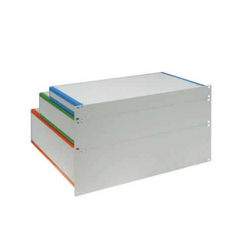
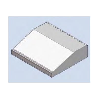
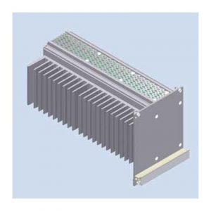 This cassette is designed for passive cooling of electronic sub assemblies and systems. The thermal power loss which is generated in the 19“ cassette is dissipated by a heat sink which also serves as sidewall. The heat sink is covered by an asymmetric front panel. Euroboards are being fitted into card guides which can be snapped in every possible position in the cassette. A wide range of accessories, for example rear cover, handle and handle strip in different colors and types are available. The front panel can be fitted with RFI springs to realize RFI shielding of the front of the subrack. Optionally the complete cassette can be RFI shielded.
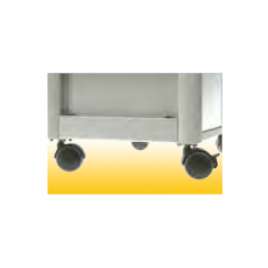 Kit consists of: 2 mounting angles 4 castors Installation hardware
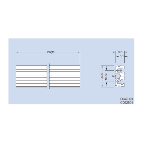
 Quick Overview Center Profile ME1 Mounted in the rear of a 6 U subrack (type alpha). Material: aluminum Finish: anodized or colorless chromated
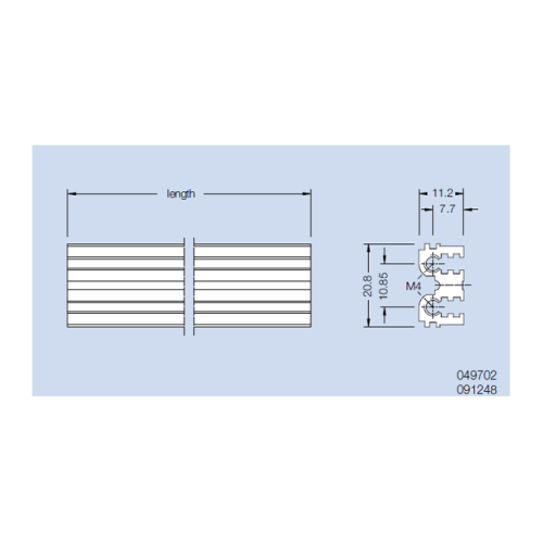 Quick Overview Center Profile ME2 Mounted in the rear of a 6 U subrack (type delta). Material: aluminum Finish: anodized or colorless chromated
 Quick Overview Center Profile MZE Mounted in the rear of a 6 U subrack (type beta), With integrated connector attachment. Material: aluminum Finish: anodized or colorless chromated
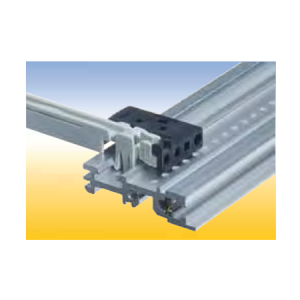 Snapped on the head of standard card guides to comply to the requirements of the specification IEEE 1101.10 Functions: 1. Holding the IEEE contact spring for grounding the alignment pins of the front panel. 2. Adapting the IEEE coding pin. 3. Guiding the 1.6 to 2.4 mm thick PCB.
 with 16 possibilities consists of: 4 coding elements and mounting parts
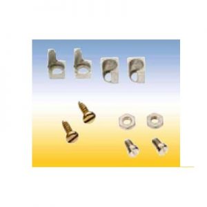 with 32 possibilities consists of: 4 coding elements and mounting parts
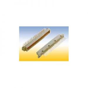 Connectors style B
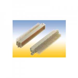 Connectors style C
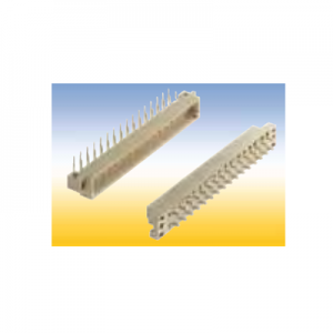 Connectors style D
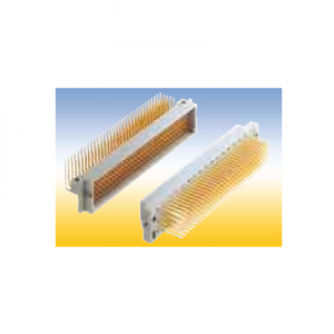 Connectors style E
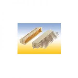 Connectors style F
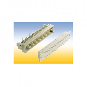 Connectors style H
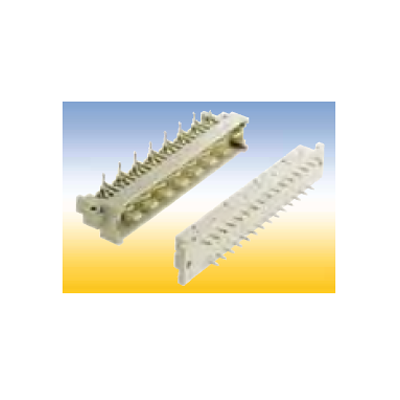
 Connectors style H
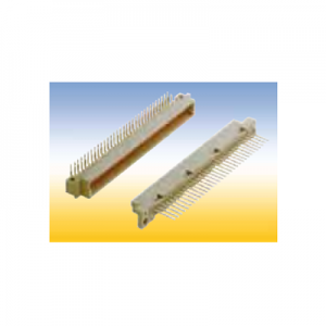 Connectors style R
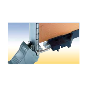 Contact Spring IEEE Snapped into the IEEE card guide or IEEE coding head to ground the alignment pin of the front panel. Material: tin-bronze order no.: 409. 113 450
 Cover Plate Fs, slide-in Hole diameter 8.5 mm. The cover plate slides in special slots in the profiles. Material: aluminum, 1.5 mm thick Finish: blank, seawater resistant
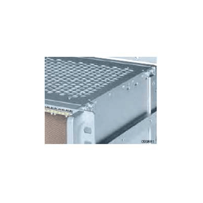 Quick Overview Hole diameter 8.0 mm. The cover plate is mounted with self tapping counter sunk screws at the side panels and at the horizontal rails. Material: aluminum, 1 mm thick Finish: blank, seawater resistant
- Quick Overview Hole diameter 4 / 5.2 x 4 mm. The cover plate is mounted with self tapping counter sunk screws on the inside of the side panels. Additionally the cover plate is secured to the horizontal rails by clips. Material: aluminum, 1 mm thick Finish: colorless chromated, seawater resistant
 Overview Hole diameter 4 / 5.2 x 4 mm. The cover plate will be mounted with self tapping counter sunk screws outside of the side panels. Additionally the cover plate is secured to the horizontal rails by clips. Material: aluminum, 1 mm thick Finish: blank, seawater resistant
- DiVar Desktop Housing with keyboard area Delivery 4 profiles 4 cover plates 2 side plates Assembly hardware
 Quick Overview DiVar Desktop Housing with keyboard area Delivery 4 profiles 4 cover plates 2 side plates Assembly hardware
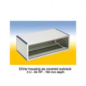 The special design features of the DiVar housing:
- It consists of profiles into which aluminum, sheet steel, stainless steel or plastic panels with a thickness of 1.5 to 2.5 mm are inserted and, if desired, secured with screws. A wall panel at the rear and a panel at the front are screwed to the profiles.
- The flexible design allows variable configuration of the housing geometry in all three axes, this allowing adaptation of the housing to customer specific requirements.
- Different surfaces can be selected for an individual appearance.
- The proven RFI contact spring concept ensures optimum RFI shielding.
- Rails with threaded holes can be pressed into the profile grooves, for example to screw in PCBs or mounting plates.
- The extensive range of Intermas accessories allows unrestricted configuration and installation of both standardized and non-standard components.
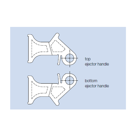
 Ejector Handle The ejector handle extends through the front panel and is screwed together with the bearing bushing at the front connector.
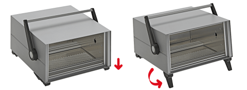
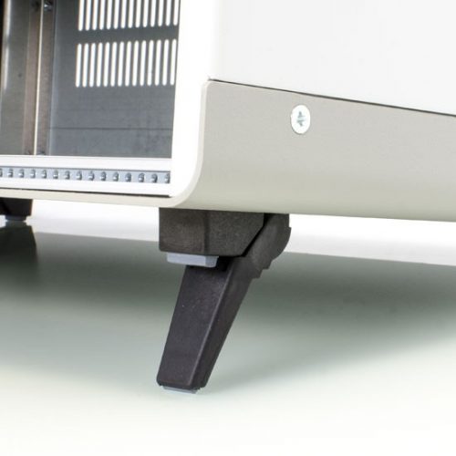
 Feet Kit: 2 feet with tip-up 2 feet without tip-up 4 self-tapping screws Material: Ultramid Purchase Online: 409-059-640-Q10 Feet Kit Package
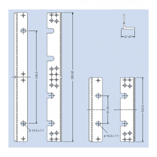 The flange can be mounted to the side panel by means of the mounting screws for the horizontal rails. Material: aluminum, extruded Finish: anodized
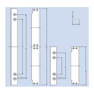 Flange for Wall Mounting For mounting of a subrack on a wall. Material: aluminum Finish: blank, seawater resistant
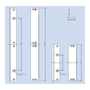 This flange is suitable for mounting of a continous front panel of 85 HP and a hinged front panel of 85 HP in a subrack. The flange will be mounted to the side panel by means of the mounting screws for the horizontal rails. Material: aluminum, extruded Finish: colorless chromated
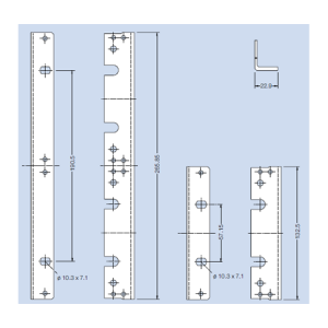 Flange without Nose This flange can be mounted at various depth on the side panel grid. Material: aluminum, extruded Finish: anodized
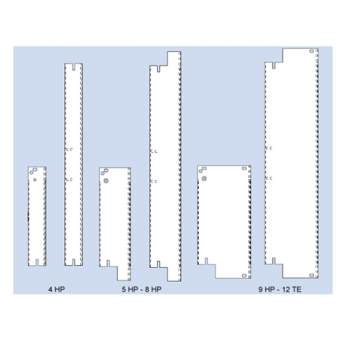 Front Panels with IEEE Handle For easy pull of PCB’s with high density connectors accordance specification IEEE 1101.10. The assambled handle kit is stuck in the milled space of the front panel and is secured with a clamped spring. Afterwards the PCB are screwed on the intergrated front connector. Two versions with IEEE handle are available: 1. Flat front panel RFI Front anodized, rear conductive. With slits in the side edges for insertion of RFI springs. 2. Extruded front panel RFI Made of extruded aluminum alloy, with slits in the side edges for insertion of RFI springs or for contacting. Surface finish is colorless chromated.
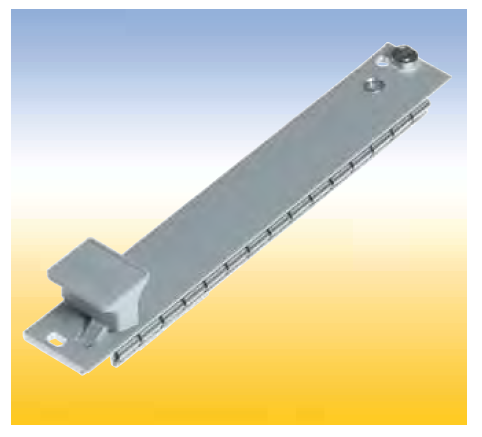
 Front Panels with Ejector Handle For easy release of PCB’s with high pin connections. The ejector handle is extends through the front panel and is screwed together with the bearing bushing at the front connector. Four versions are available: 1. Flat front panel blank. The front side is covered with a removable transparent foil. 2. Flat front panel anodized. Front anodized, rear conductive. 3. Flat front panel RFI Front anodized, rear conductive. With slits in the side edges for insertion of RFI springs. 4. Extruded front panel RFI Made of extruded aluminum alloy, with slits in the side edges for insertion of RFI springs for contact. Surface finish is colorless chromated.
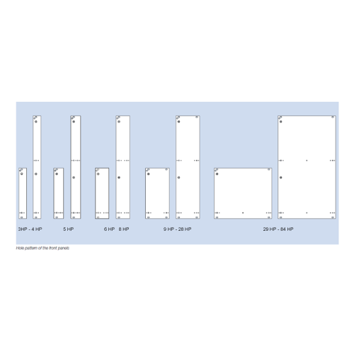 For assembly on a PCB. Handle and front connector are screwed on the front panel. The plain front panel is easy to modify. Four versions are available: 1. Flat front panel blank The front side is covered with a removable transparent foil. 2. Flat front panel anodized Front anodized, rear conductive. 3. Flat front panel RFI Front anodized, rear conductive. With slits in the side edges for insertion of RFI springs. 4. Extruded front panel RFI Made of extruded aluminum alloy, with slits in the side edges for insertion of RFI springs for contact. Surface finish is colorless chromated.
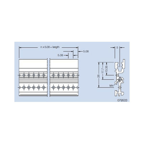 Front Profile VE1 (also rear profile by using of a front panel on the rear). Material: aluminum Finish: anodized
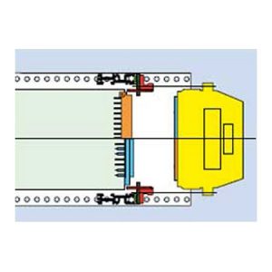 For interface housings with female or male connector, for mating di rectly to the PCB (LP) connector. Installation in the wiring field of the subrack.
 Guide component F for mounting of a 3 HP metal interface housing in any position of the mounting area.
 Guide component F for mounting of a 3 HP metal interface housing RFI in the upper or lower area of 6 U subracks.gers.
 Guide component F with integrated front panel for mounting of a 3 HP metal interface housing RFI in a 3 U subrack..
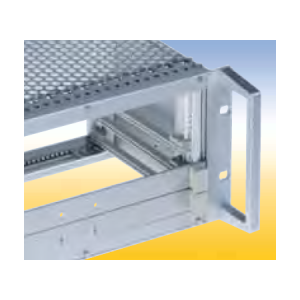 Material: aluminum Finish: anodized
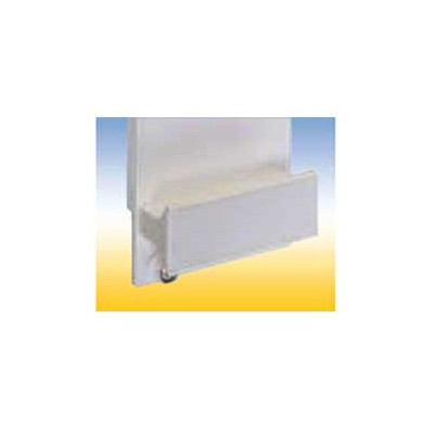 Handle FP Assembled with M 2.5 screws and with 1 additional self tapping screw from 6 HP. The handle is held against torsion by means of two nipples.
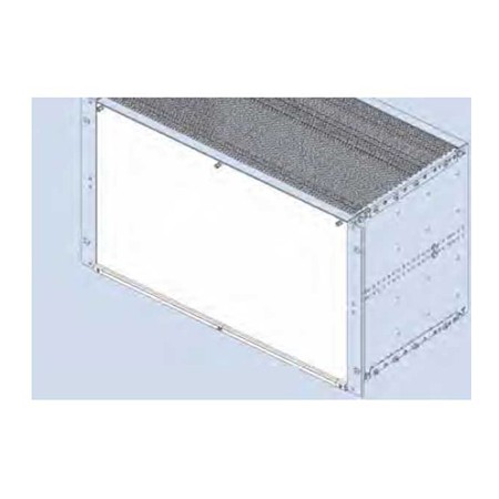 Hinged Front Panel 85 HP With slits in the side edges for insertion of RFI springs. The hinge is screwed to the profiled rail of the subrack. An 84 HP threaded strip is needed. To be used in combination with below mentioned flanges only. Finish: front side anodized, rear side conductive Delivery: 1 front panel 1 hinge 3 grounding bushings Mounting parts Delivery: as unassembled kit. Assembled kits on request.
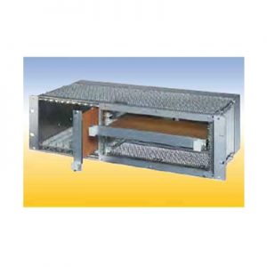 20 HP for horizontal mounting of 6 U PCB‘s in 3 U subracks. The horizontal mounting frame needs 52 HP in the width. For 84 HP subracks are available Placed right: 52 HP for horizontal mounting frame, 32 HP for 3 U PCB‘s Placed left: 52 HP for horizontal mounting frame, 1 HP for air and leakage paths, 31 HP for 3 U PCB‘s.
 Ident Plate for handle FP. The ident plate is markable and printable, snapped in after mounting the handle to the front panel.